Sunday, October 1, 2017

Athearn Blue Box DD40 Rebuild

Athearn Blue Box DD40 Rebuild


Making my MP40


I've been working on this MP40 for a couple years now.  Lately, I made some 3D printed parts to help me out.

I need better pilots and a better cab stand, so I used a Mecreator 2 to make these basic parts and they turned out pretty decent.

I used PLA to make the parts and found out that PLA is hard to sand.  In the pictures below, you'll find that the surfaces are a bit rough and the accuracy is not that great.

This project is mostly a learning project and not meant to win any contests.  I do have several more DD40's that will build on this concept and their accuracy should be much higher.

The next step from here is to use wood filament rather than PLA.  Parts printed with wood should be much better for finishing.

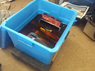
First up we have an orange box Athearn DD40 dual motor that needs quite a bit of restoration:

A top view of the MP40 Hercules:


 The rear, you can see how the 3D printed parts are very rough and will require quite a bit more work to get right.  Also the air enclosure.  It's big, but rough around the edges:

MP40 Hercules

 The xy milling table, a very handy tool.

Friday, September 15, 2017

Researching the Chicago and Northwestern Railroad in Iowa and Minnesota

Researching the Chicago and Northwestern Railroad in Iowa and Minnesota

Tools and Techniques

The Fairmont Subdivision Part 1


The question on a Facebook group was "How does the line from Vesta MN to Burt IA tie into the Fairmont Subdivision on the CNW?"

I remember an issue from the 1990's of the Northwestern Lines dedicated to the Fairmont Sub...but I don't have it handy, so once I pull it out of my archives we can see what it said.

Using http://www.openrailwaymap.org/ I checked the status of the rails to confirm that the track at Vesta had been razed, probably a very long time ago.

In CNW System Timetable 1 from 1972, the track at Vesta runs to Wabasso and then west to Marshall.  Sometime before 1972 the line from Vesta ran to Butterfield, which would have made it part of the Fairmont Sub.

At Fox Lake MN that line continued to Burt IA and on to Algona.  The CNW Burt Sub ran from Eagle Grove to Ledyard, but at Burt Yard limits were in effect all the way to Ledyard in 1972. In 1981,according to CNW System Timetable 5,  the Burt Sub ended at Bancroft.

Today, using Google Earth Pro with the railway overlay turned on, you can see the line ends south of Bancroft where the river bridge was taken out and is now used for the storage of grain cars.  OpenRailway shows this as the Jewell Sub of the Union Pacific.

You can still see the roadbed for the tracks that ran from Burt to Fox Lake.

Back in Vesta, in 1972, Yard limits were in effect from Marshall to Vesta on the Wabasso Sub.  In 1981, it was all gone.

What we need to do is fill in the blanks from Vesta to Burt and then figure out how that line tied into the Fairmont Sub at Fox Lake....

We also need to tie in the Chicago Milwaukee and Omaha sub that ran from Lake Crystal MN to Burt IA.

So here's our first working map:


Next up, we'll consult the timetables....

Sunday, July 2, 2017

Tyco Super 630 C630 Power Torque 3D pilot stl file free

Tyco Super 630 C630 Power Torque 3D pilot stl file free


Making a pilot for Tyco locomotives can be a challenge.  You need a solid hard point to mount couplers, preferably with a 2-56 screw.


This simple stl file fits right place and allows you to drill a hole to attach couplers....


Here's the link:

Tyco C630 3D Pilot STL file

Thursday, June 1, 2017

Matchbox and Hotwheels Trucks Compared to HO Scale

Comparing Matchbox and Hot Wheels to HO Scale

Part 1 - Matchbox F550 Super Duty and Hot Wheels F150


You see a lot of questions but very few answers when it comes to using Matchbox and Hot Wheels with HO Scale.  Some people do it all the time and others don't want to have anything to do with it.

Before we get started, I want to direct you to watch the Hot Wheels restoration video, which is probably the best video out there for beginners in this area.

Credit goes to Angelo Bonsignore for getting me started on the path to restoring my old Hot Wheels.

His channel is here:  Angelo Bonsignore YouTube

The specific video you should watch is: How to restore Diecast Cars

Once you've seen that it can be done with very good results, then the trick is to find models that can work.

Specifically I'd like to find models that are available today for the classic price of $1 at every place that sells toys.

Recently I picked out a Matchbox F550 Super Duty and a Hot Wheels F150 Pickup.


The first thing that is easily noticed is that the F150 is much bigger that the F550.  Some of this is due to the bigger wheels, but overall the body is bigger on the Hot Wheels model.

First let's check the measurements of the Matchbox F550 compared to the listed specs of the real thing:

Ford F550 Super Duty
Matchbox F550 Super Duty
Percent Difference
Wheel Base
14'4"
13'5"
94%
Length
22'8"
21'2"
93%
Width
6'8"
6'3"
94%
Height
6'9"
7'2"
106%
Tire Size
33"
34"
104%

This model is scores an actual accuracy of 98% average.  This truck is worth trying to make it into a better model.  With that high average it should fit nicely into most scenery.

Next up the Hot Wheels F150 Super Cab:

Ford F150 Super Cab
Hot Wheels F150 Super Cab
Percent Difference
Wheel Base
13'7"
14'3"
105%
Length
20'11"
22'3"
107%
Width
7'2"
8'10"
124%
Height
6'7"
8'10"
135%
Tire Size
33"
45"
135%

The total average accuracy of this model is 121%, which in general is going to big too big unless it's an isolated scene.

What we've learned in this part is that a closer look is needed at Matchbox and Hot Wheels.  Even though the F150 is too big, there are other trucks from Hot Wheels that need a closer look.

One of the next things we'll need to do is make a mold of some of the best wheels we can find to really dress up some of our findings.

Saturday, May 6, 2017

Walthers Northern Light and Power

Walthers Northern Light and Power


While we're working on the AHM GP18 rebuild, there's also some structure making going on....

I picked up 2 Walthers Northern Light and Power Buildings at a train show for $10.  Now these 2 buildings were on sale cheap because they're HO scale and I was at a show that was mostly O gauge.

Both of them had all they're parts welded on with orange tube testors glue.  I used and wood door shim and a hammer to dismantle as much of the buildings as I could.  All the windows came off nicely using this method.

I painting all the remaining parts with brown primer and then used the airbrush with Rustoleum Sunrise Red.  Then I used a wash of Testor's black gloss with a lot of mineral spirits.  The buildings are turning out nice.

One of them had an addition of interior details.  I have to wonder why you would model an interior, but not allow it to be seen by welding on the garage doors and frosting all the windows.

I decided that I needed windows that you could actually see through.  So I fired up 123d and made some windows and printed them with my 3d printer.  They turned out pretty nice....

Let's take a look:


That's how you do it.....


OK let's look at the new window frames that let in a lot more light so you can view the interior....


That's how you do it......


Friday, April 21, 2017

HO Scale AHM GP18 total rebuild Part 1

HO Scale AHM GP18 total rebuild Part 1


Stripping the paint and making some parts


We're going to take an old school AHM GP18 and totally rebuild this guy and make some 3D printed detail parts to pimp out our build.

The AHM GP18 from back in the 1970's was many kid's first locomotive, mine included.  I've always loved this model for that reason.  They are super easy to find for very little money, but have a reputation of being unreliable.

There are 2 reasons for the unreliability.  First, this toy was meant to take abuse at full power being reversed at full speed over and over again.  For that task, this engine was pretty good.  The motor takes a lot of full power abuse.  It wasn't expected that it would be used for slow speed switching with short moves and delicate situations.  The motor likes to get lots of power to get going and stay going.

This leads to the second weakness, power pickup is poor, using small wipers.  The wipers are on alternate sides, so you don't get power from all the wheels.  Dirty wheels and wipers lead to jerky operation and no real slow speed ops to speak of.

We're going to do a real budget build on one of these to include a new motor with good slow speed and low power operation. We'll also fix the power pickup problem.

We're also going to make a couple 3D parts from scratch and handrails from brass wire make this an interesting locomotive.

Hopefully by now you have the skill to tear this thing down to bare bones.  Carefully remove the 3 screws you will find on the underside, 2 by the cab and 1 on the fuel tank and take it apart.  Remove the sideframes and truck clips carefully with a small flat head screwdriver without breaking anything.  Pinch the motor clip from underneath carefully to release the moter.  Cut all the wires since we're rewiring it anyways.

You should be taking pictures before you do stuff so you know how it was in case you need to put it back together, but I'll have pictures and instructions here to help you.

Take apart the trucks without breaking the tabs.  Use very gentle pressure on the plastic tabs and clips to do this.  You might have one that was oiled with something that made the plastic brittle and things break off.  DO NOT PANIC.  We'll deal with broken parts later.

Use Dawn dish soap to wash everything to remove all oil, dirt and grease.  Don't lose any gears down the sink.


OK, you can see it apart.  That yellow motor is the possible replacement from ebay for about $2.  Don't know if that one will work yet, but we're trying it.  I started cutting off the handrails.  There are side pieces that will be glued to the shell.  They are removed by gently scoring the line where they meet the frame many times with a knife.  After each score, bend slightly back and they will eventually come off nicely.

We'll go in depth on the gears in another part, for now we want to strip the paint.

This paint is tough to remove, so I used the EZ strip method from the previous blog post.  Go review the 5 methods before stripping the paint.  On this particular shell, the yellow is very tough to remove, so EZ strip was the way that worked.  There were 2 spots where I left the stripper in place for about 5 mins and it started to melt the plastic.

DO NOT USE EZ STRIP ON THE FRAME.  It melted a section of the walkway right away.  The rubbing alcohol method works on the frame, but it takes 2 days or a little more.


I'm going to make some beefed up fans and exhaust mufflers using the 3D printer.  We'll save that for another part of this project.  At this point I glued on 2 of the battery box covers I cut off the frame, but the 3rd piece has nothing to attach, so we'll make something to glue it a little later.

We'll get to the paint in another part, so at this point you should have your shell ready for painting.  Make sure to wash it with both the tooth brush and a soft cloth with soap to get all the stripper off.


Stripping paint from Model Trains and Locomotives 5 Methods

Stripping paint from Model Trains and Locomotives 5 Methods


How to remove paint from models


There are several methods to remove paint from models.  Each method has it's own risks and effectiveness.

I strip a lot of old locomotives and a few freight cars - here's how I do it:

Method 1 91% Rubbing Alcohol

I use a tub with a top, tupperware is good for this.  Pour in as many bottles as it take to submerge the shell you want to strip.  Highly effective on newer paints that are much thinner than the old school toy paint jobs...
Let soak for as long as you need to, sometimes days or weeks, but in the case of modern paint jobs it can be as short as an hour or 2.

I had a locomotive that was primered with gray auto primer in there for a few weeks.  I noticed that the paint wasn't coming off, but it was bubbling a bit.  I took it out and placed it in front of a fan and the fast drying action caused all the primer to flake off.  That would be a rare case, but you never know unless you try it.

The rubbing alcohol method usually leaves the plastic intact with no damage, but I have has shells that developed striations, very rare though.

It must be 91% rubbing alcohol.  Use this method first unless you know the paint really well and know it won't work.

Method 2: 8% (or higher) pine oil

Pinesol will NOT work for this, it doesn't actually contain real pine oil.  Fortunately the bargain brands at Walmart say on the bottle that they contain about 8-9% pine oil and they are much cheaper.

I use a 5 gallon tote box to do this.  This method can take weeks to work, but sometimes overnight will do the job.

I keep the oil, which is very heavy, in the tote and on top of a 4 wheel dolly.  Even with the lid on, I put a large bath towel over the box to keep it from stinking up the place.  This method works pretty good on toy type paint jobs, but takes quite a while.  The make it work faster, clean the shell each day with dish soap and a stiff tooth brush and put it back in.  I often put future projects in here and leave them for sometimes months until I'm ready to use them.  I haven't noticed and plastic damage from this method.

Method 3:  Brake Fluid

For really tough paint jobs, brake fluid soaking can often do the trick.  There are shells that can be attacked by the brake fluid, but in general it works pretty good.  I've soaked many shells for weeks in brake fluid and it will remove some of the toughest paint I've ever encountered.  But, try method 1 and 2 before you resort to the brake fluid.

I double bag the shells and don't submerge the shells, I let the fluid spread through the bags.  I place the bags in a tupperware container, but don't seal it up.  Just roll the bags shut around the shell.  Check within in the first hour, then everyday until you are comfortable with this.  Works best on toy paint.  Frequent cleanings help, but this method increases the risk of melting a shell.

Method 4: EZ strip

I got this stripper at Home Depot.  There are many others that will melt the plastic, especially the citrus strippers.  EZ strip will also melt the plastic so you have to actually sit down and do this one by hand a little at a time with a tooth brush.  Frequently spray with a soap and water mix like 409 or spray and wipe and then wash in dish soap with a tooth brush.  Many small applications will do the job.  Don't turn your back on any section with this stuff applied or it will melt the plastic.

Many washings with dish soap in between small area applications of EZ strip.  Very effective, but very high risk.

Method 5:  Oven Cleaner

This is how we did it back the 1980's.  I say don't use this method, I've melted shells many times doing this. But, if you must know how, then what you do is heat the oven to 100 and use a cookie sheet.  Spray the shell with oven cleaner and put it in the oven for a couple mins at most, take it out, wash it and do it again.  Takes off most paint, but melts plastic more than 50% of the time.  You can do it without using the oven in a plastic bag, but that almost always leads to striations in you plastic.

Bottom line:  don't use the oven cleaner method, too much risk.

There are also model products you can buy to remove paint, I don't use them, but I've seen that they are generally very good and effective.

So why go through the trouble of these other methods?  Simple, they are much cheaper and the first 2 are just fire and forget methods - drop the shell in and come back when you're ready for it.  Otherwise, you can buy the good stuff and do it right now.


Thursday, March 30, 2017

Use LED lighting quick and dirty simple step by step

LED Quick & Dirty Guide Step by Step

Explaining how to use the Light Emitting Diode

Make an LED Ring tool

Quick & Dirty Guide to LED's...
Using your power pack, you can connect the DC or AC or Track Power DC to a string of LED's and get them to work reliably.
Make an LED Ring Tool so you don't have to memorize how to do LED's and have a tester for brightness.
We're going to keep it as simple as possible. If you can get these things, you can light up your LED's in a matter of minutes.
Tools needed:
1. Solder Pencil/Iron/Gun - a simple $10 solder pencil from the auto parts store (or Home Depot, Lowes, Menards) will work for most things you do.
2. Solder - electrical rosin core is what I use (Home Depot, Lowes, Menards) about $4
3. Rosin Soldering Flux Paste - I use RadioShack, at Grainger it's $2. You CAN use most kinds of flux, but rosin is best for electrical.
We'll explore different kinds of flux later, for now get what you can to make this project work today.
4. Bridge Rectifier - Radio Shack (if you still have one) or ebay or Amazon. You might luck out and be able to find one at some other store near you. on ebay $7 for 10 600 volt, pretty good deal.
5. 1k resistor - online or some auto parts stores, on ebay 100 1/2watt are $3.48. Sometimes I use 1 watt and sometimes 1/4watt, if you pop an LED, then you know it was the wrong resistor.
6. LED of your choice. Brightness is measured in MCD. I have some that are 700mcd, 7000mcd and superbright at 24000mcd, almost like a surefire flash light. We'll play with brightness later.
We need to make this ring so we can test LED's to see if we like them in our projects.
Once you have a working ring, you can then add new LED's to see how bright they are compared to others that you already know.
Here is a useful note: A 5mm led is just a little too big for an Athearn blue box Trainmaster headlight and a 3mm is too small.
Make the ring:
1. Tin your parts. This is where you pre-solder the parts leads so they are easy to join to another part.
2. Join the "+" lead (which is marked on the bridge rectifier) to the resistor. The GOLD STRIPE IS toward the next part. You are soldering the "+" to the side of the resistor without the gold stripe.
3. Look at the pictures below - inside the LED is a big piece and a little piece, solder the gold stripe side of the resistor to the small side of the LED.
4. Put more LED's in the same direction, small side always points back to the gold stripe.
5. Solder a black wire from the big side of your final LED to the "-" lead on the bridge rectifier.
6. Connect power from you power pack and light them up.
I like yellow for the inside of building and some headlights. You can use the AC accessory on your power pack to do this.
Remember those old power packs you have somewhere? You can use those to light city blocks.
In locomotives without DCC, you can use this LED ring to do you lights. DCC already has circuits that deal with lights, so this isn't for use in that situation.
Passenger cars, EOT - end of train, all that is possible from this.
This is only the beginning. You can get much more complex but adding other things to your ring, but you'll always have an example of the basic working LED.


Saturday, March 25, 2017

HO Scale Bachmann Pancake Motor Rebuild Part 3

HO Scale Bachmann Pancake Motor Rebuild Part 3


1980's U36B motor restoration


Here's the final part...  The motor works, the gear repair holds and we get it up and running again...


Thursday, March 23, 2017

Rebuilding an HO Scale Bachmann U36B pancake motor Part 2

Rebuilding an HO Scale Bachmann U36B pancake motor

Part 2


Pancake motor rebuild


Here's the next episode....


Rebuilding an HO Scale Bachmann U36B pancake motor

Rebuilding an HO Scale Bachmann U36B pancake motor

Part 1

another total rebuild of a pancake motor


Here are the first 2 parts of a short series of rebuilding a pancake motor from an old Bachmann U36B.  I like doing these because they are good practice for building the skills you need for more complex rebuilds.  You can really dig into these projects without fear of ruining a $300 locomotive...


Friday, March 17, 2017

Repairing Cracked Gears with Baking Soda and Super Glue

Repairing Cracked Gears with Baking Soda and Super Glue

HO Scale Bachmann Old School Pancake Motor Repair


I've been advocating gear replacement a lot lately.  That is the preferred method, but sometimes you just need to repair and existing gear.

You may have heard the legend of the baking soda and super glue repair method.  If you haven't, then it goes like this:  you can combine baking soda and super glue into a paste that can be used to repair gears that are impossible to find a replacement for....

That is mostly correct, but how you actually do it is to fill the crack with a fine dusting of baking soda and apply a tiny drop of super glue and it will create a super strong weld.

While rebuilding another pancake motor from a Bachmann U36B, I did discover 2 cracked gear and decided that it was time that someone demonstrated the legend.....

Here is a video demonstrating:


Tuesday, March 7, 2017

Rebuilding old Bachmann HO scale U36B Part 8 finishing the handrails video

Rebuilding old Bachmann HO scale U36B Part 8 finishing the handrails video

handrails installed

Finally we got the the handrails installed and some white safety stripes painted here and there.  This build is now operational, anything else we do from here is just an improvement.

Check out the final handrail video in this series:


Saturday, March 4, 2017

Rebuilding old Bachmann HO scale U36B Part 7 the handrail videos

Rebuilding old Bachmann U36B Part 7 the handrail videos

making HO Scale handrails from scratch out of brass....the videos


I've made a video that is so long, that I'm already on part 4 and over and hour and still not done uploading it all.

But while you're waiting here are the first 4 parts....

Part 1 The Introduction for only the newest of n00bs

Part 2  Stanchions

Part 3 Endrails
Part 4 First Solder and Shape

We'll finish up in the part 8 with the final videos.....

Thursday, March 2, 2017

Rebuilding old Bachmann U36B Part 6 Brass Handrails

Rebuilding old Bachmann U36B Part 6 Brass Handrails

making new handrails from brass wire


We're at the point where we need some handrails for our U36B project and they way we're going to do this is with brass wire and solder.  We'll be using K&S wire #8159 .020in from Hobby Lobby at $1.49.  4 Pieces will be just enough to do this without wasting the wire.

In the old days, I used to do this out of piano wire which is even cheaper, but much harder to bend.  I don't know how I ever had the patience to bend that stuff, but it can be done.  Piano wire is pretty tough to solder also.

We aren't going to do a lot of measuring to make these handrails.  Remember that our goal here is to finish a model good enough to go on the "C" list.

The A list is all your rock star scratchbuilt super detailed contest winning most excellent pieces.  The B list is your customized factory super detailed $300 locomotives that you don't feel comfortable about throwing into a tub of pine oil.

Then there is the C list.  These are your supporting cast members, the extras, that 3rd or 4th locomotive in the consist during a photo shoot.  It's one of the workhorses in an operating session.

Being a workhorse means having handrails that are more durable than the latest slippery plastic scale handrails. Those handrails don't take a lot of abuse and seem to always be wavy somewhere...

First let's measure up a bit, here's a pic of a prototype that will guide us in the employment of our Mark I eyeball....
This photo shows us that the handrail should cross by the rear grill and the top of the rail in front should be lined up nicely with the words on the front.  Using the ruler, that means a rough hieght of .5 inches above the deck, but we're still going to do this be eyeball and stay away from the ruler as much as we can.

Once we make a rail, then we can line it up on the cutting board and copy it using the ruler lines on the board which is much easier.

First we need to drill some holes for the stanchions.  I'm going to use a drill bit that by eyeball looks real close to the size.  I could have gone to the Hobby Store and got a matching drill and wire set, but we should really try to use what we have on hand.  The dental pick is used to make a mark where to drill.  That's really important to prevent the drillbit from breaking.  I could have also used the drill press or dremel, but the pin vise is almost as fast with no danger of melting like a dremel.
Now we need to drill 28 holes and check to see that the wire fits....it does: 
Using the prototype picture and an alcohol marker and steel ruler ($4 on ebay) I determined the .75 inch stanchions were more that long enough.  We need them to be just a bit long so we can shape them later. 
 Now the stanchions are cut, so lets bend a foot on 20 of them, leaving 4 vertical stanchions for each end.  The end stanchions go straight into the anti climber from the top.
When all are bent it should look like this: 
 Now we take a long section and bend the back end first.  Put the foot on it and then make a mark where to bend it for the long section.  Make the bend and check to see if it's good.  It probably will be off a bit so unbend it and do it again.  You'll get it and then you can make a mark where that short bend goes near the cab.  It may take a couple tries, but once you have it, you can trim it and then we'll get ready to copy it.
 Here's just a check look to see if what we've done is roughly what we had intended...
 Next, we aren't really repeating the process for the other side, we're copy the bends on the cutting board using the blue lines then checking them on the shell.  Way easier than doing another totally from scratch again.
 Starting to look pretty good...
 Same technique in the front.  You can make as many fancy bends as you want here, right now I'm just doing the basic bend.  Once ready, we copy it for the other side.
 The front looks pretty decent, we can copy it on the cutting board for the rear.  At this point you should be getting pretty good at marking spots to bend and making a good bend.  If it's wrong, you straighten it and do it again.  It's ok if the wire gets beat up without breaking, it actually gives it a bit of character.
 The parts are made and now we can move to the soldering bench...


Tuesday, February 28, 2017

Rebuilding old Bachmann U36B Part 5 Weathering

Rebuilding old Bachmann U36B Part 5 Weathering

1 color panel line pin washing


If you haven't figured out by now, my trains are inspired by the Minnesota Commercial Railroad, so my weathering is based on photos I took of the real deal....

The effect I'm going for in this build is sort of like this B30-7 I found in St. Paul...

my gallery of Minnesota Commercial can be found here:


Here is where we are with our build:


I used Testor's Gloss black and mineral spirits to just dab at the panel lines and let the paint flow where it will.  Then I used either my finger, a cutetip or a paper towel to wipe off the excess.

I'd say for this low detail build we are looking pretty good and can now go ahead and spray a gloss sealer on it.  Then we can move on to the handrails.

For a detailed look at how the real pros do this, here is my favorite panel line pin wash video:


This guy knows how to do it.  He uses a pretty expensive pin wash, where I use just plain Testor's.

Rebuilding old Bachmann U36B Part 4 Decals

Rebuilding old Bachmann U36B Part 4 Decals

Modern Decals for the Vision Impaired Modeler


Each month I participate in an operating group that really gets quite sophisticated.  Not having the best vision is a problem.  So you wear glasses on your nose or bifocals.  Comparing your switch list to cars on the track at around 3 feet away gets to be a problem.  Better yet is when you think your car is in the middle of a train that's in the middle of a yard and you want to look between cars to spot a number.

Years ago I decided I wanted to do the opposite of what most railroads do.  I'd have a big number and a small logo.  The problem was making decals for big numbers.  And the most pressing problem, making them white.

I used to do a lot of commercial photo printing and have 2 large format high resolution photo printers.  I was convinced that I could learn to print the best decals that could be made.  You can go back to June 2016 to read my series on making decals.  Since then, I've gotten my ALPS MD-1000 working great for white decals.

No printed decals can match the strength of white decal paper.  They just can't, so when it comes to large white decals the best way to go is the Cricut.  My Cricut Explore is what I use to make exactly the numbers that I want when I want them.  I don't need to assemble my numbers from a sheet of general numbers.  I just cut them.


Once they're cut I can apply them.  What I use is 1 drop ammonia and then a jar cap about 2 inches across and half inch deep.

Large decals can be hard to work with.  A Cricut spatula works for the big decals and I use an xacto 17 flat blade for small decals.  Use quite a bit of water and place the decals.

Position them all...plenty of water, if you screw up, put it back in the water...

Now let them dry out pretty good BEFORE you use Solvaset.


Now a little solvaset at a time, big decals tend to wrinkle up, so little by little...


While we're waiting, let's do some number boards in Freehand....

30 years ago, I painted the number board position white, cut individual numbers, 4 sets of them, and placed them on the white and then put a clear decal with black border over the top.  Yes, they looked good and still do, but that's too much work considering I can do this:
 I used my machinist's ruler to measure the number boards then typed the data into Freehand.  A sheet of Epson Premium Glossy photo paper and I get this:
These numbers will look awesome for something like 300 years according to Epson...

White glue is the appropriate glue to attach photo paper to plastic.  It will dry clear which renders mistakes invisible.


Now that looks pretty good if you ask me.