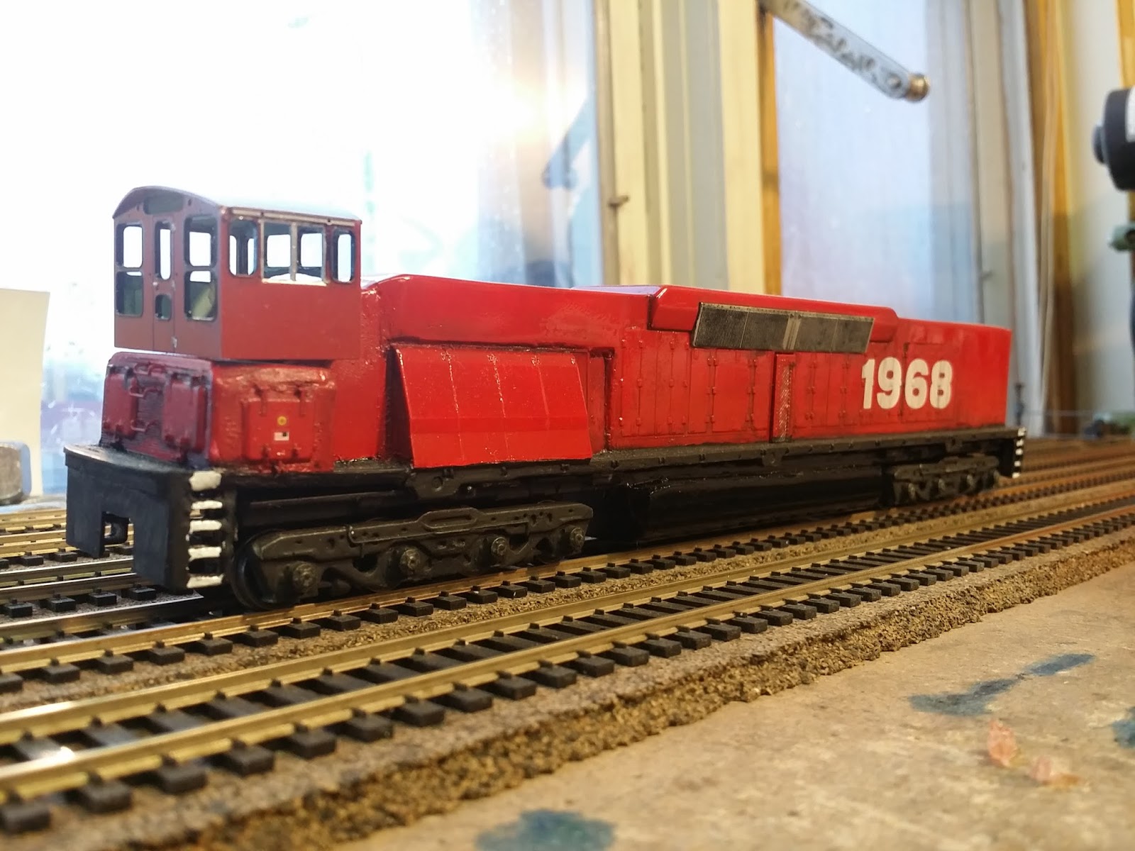
Bachmann High Nose GP50 pancake motor
&
Life-Like High Nose GP38-2 pancake motor
Multiple Unit Build
I've got these 2 locomotives that I found at train shows. They both have the infamous and notorious pancake motors. A few years ago I airbrushed them with Rustoleum Gloss Red Enamel. The paint jobs are actually pretty good, but did take weeks to fully cure. I also put the decals on and number boards. Then they sat in the junk pile for about 5 years.
I got the idea that I could use a 2 pin connector and make a connection between the two locomotives so that they would share power. The reason is that they have plastic front wheels with traction tire and only get power from the rear truck. Yes I could have replaced the wheels and made it all-wheel pickup, but I've lately been trying to think of ways to improve the original system without investing into replacement parts.
I rebuilt the motors to better than new performance. In fact, the motors, despite being damaged and beat up, have come back to life in the most amazing way. I've always believed in the pancake motor concept because it's proven itself in slot car racing. The motors in DVD and CD-ROM drives are pancake motors with a better enclosure and more modern cores, but they are still pancake motors. I'll probably be using one of those motors from an old DVD drive on a Bachmann steam engine that I've got sitting in the deadline.
So the concept of this operation is to make a PC board that collects power from the pickup truck. Then power is routed to the motor. But, a set of wires with a 2 pin quick connector will also be on that PC board. The male connector will be on the outside of one of the locomotives and the female with a bit of the wire leads will be on the other. When connected, the 2 locomotives will be sharing power pickup from 2 trucks instead of 1 truck each.
So let's see where this takes us....
Clean the wheels, polish them and paint the ends if you're going to do that now. Clean any paint off the part that touches the rail. Coat the back and tread area with Oxgard - it will stay greasy for a couple weeks then turn to a film.
Wipe a paper thin layer of red lithium high temp brake grease - which you get at any auto parts store in a little tub that will last decades - into the sockets that hold the axles. No more than a paper thin layer and no excess.
You will lay the wheels into the centerpiece after the wipers are installed - but do not put the side frames on. When you get to the phosphor bronze wire step, carefully set it upright without the sideframes on and with the wheels in place.
Rebuilding the power pickup trucks is one of the more difficult challenges. The idea is to keep the copper wipers exactly as they are built. They need to be cleaned with new black and red 32 awg silicone wire soldered to them. Then they must be coated with Oxgard. The new leads are threaded through the existing holes like usual. But, before doing any of that we need to make a modification for the new parts we're going to make. Look carefully at the truck and you will see a small hole where the wire gets threaded into the center so it can go up through the frame. You will need to take a 1/16" drill bit and make a second hole that mirrors the one on the other side. You will be drilling 2 holes, 1 on each side so that when you are done you will have holes that match. This is super simple but hard to describe, there will be pictures later. Look at the truck and see the holes that it came with are drilled near the axle socket. You will make 2 new holes in the same way near the other socket - like a mirror.
Now you can install the copper wipers and thread the wire - red on one side, black on the other. This wire goes through the hole that was factory made - right hand hole when you are looking at it laying on its side.
You will need a tube of phosphor bronze wire for the next step. My goto wire for this is .0125 phosphor bronze from Tichy. You will need to cut 2 pieces that are long enough to span the tops of the wheels on each side, but not so long that the sideframe can't be put back on. Lay this piece on top of the wheels and mark a spot just to the right of the hole we drilled earlier. Now tin this spot with solder and solder a red wire to one piece and a black wire to the other.
Next thread the wires through the holes we made - make sure the red is on the red side and the black is on the black side. You can't do this wrong because the center piece of the truck will fit either way, it's totally the same. Just get all the wires of one color on the same sides.
Pull the electric wire tight enough to keep the bronze wire touching the tops of the wheels. At this point you will probably need a drop of super glue to hold the electric wire tight. When you have everything they way you like it, put the side frames back on.
The pancake motor rebuild went very well. With all the parts cleaned in the ultrasonic cleaner using Mean Green, the parts looked good. The core was inspected and polished. The motor housings were thoroughly cleaned in the ultrasonic. Oxgard was applied to all the parts that needed it, but especially the screws that hold the housing and the brush covers. these screws tend to rust over time. The brush covers were polished and coated with Oxgard. It's important not to get Oxgard on the actual brushes because it can cause them to become soft. Better is to use powdered graphite inside the brush sockets to keep everything dry and free moving. Once assembled and lubed carefully with red lithium grease the testing could begin.
The red lithium gets a little stiff when cold so it helps to warm things up. Once in use, you would never believe how smooth a pancake motor can be. Also, the sound changed. The motor now sounds acceptable. The annoying high whine is much less than before. It sounds best at about 50% power. Extra weight needed to be added at strategic points to help keep the wheels from picking points due to light weight. The plastic pizza cutter wheels will reveal many track flaws. Cheap switches that have rivets holding the points will get picked frequently. At first I thought it might be a wheel gauge problem, but after checking and rechecking, I noticed that the locomotives had no problem on my hand laid switches. The problem appeared on a couple switches where I used the cheapest snap switches where the rivet is not perfect. I fixed a couple of these, but I marked them for replacement with my hand laid switches.
On the GP50 I put the socket on the rear pilot. When I wired it I kept the red wires on the right and the black wires on the left. This means that one of the locomotives needs to have the red and black reversed on the M.U. cable only. So on the GP38-2 I put a solder pad on the rear pilot and brought the wires through. This means that if I want to remove the shell I must unsolder the connections. On the GP50, I put a disconnect on the inside so I can remove the shell. One thing about the 2 pin connectors is that I shaved the off the teeth that hold the connection in place. The reason for this is that the connectors are extremely difficult to disconnect in small spaces. They are not likely to come apart so removing the locking teeth is no problem. Also in the event of some failure of couplers the locomotives will just disconnect instead of dragging themselves by the wires.
The performance of the lash-up is off the charts fantastic. Super slow, no stalls, excellent for switching ops. I would classify this as a huge success. I'll add pictures pretty quick and do a youtube video of the performance.
So.... my U36Bs.... this is what I'm going to do to them. I've pushed individual locomotive performance to the max, but with multiple units sharing power we have excellent performance. The operating reliability is so far as good as anything else and will certainly get DCC. BQ23-7s are another bunch that will get this treatment. The bonus is that locomotives can be swapped around. The AHM FM C-Liner project is now a total go - that will be a B unit with the cable on each end and the A units each with a socket.