Wednesday, December 24, 2014

Bachmann Cracked Gears and their Replacement

The Merry Christmas Edition


So as most of you already know I have a thing for Bachmann and Life-Like pancake motors.  I've said many times why I like them and detailed how to repair them.

Now it's time to take things to another level...

Cracked Gears


This is problem that plagues many modelers today.  They want to know how to replace cracked gears for whatever reason and get no help on any of the modeling forums.  Most replies are to junk the engine or turn it into a dummy or more completely unhelpful information.

I've been studying the methods used by hobbyists who fly drones.  They generally use a lot of repair parts.  Some of the frequently used parts is several types of small precision gears.  Usually it is not cost effective or their is an accuracy problem with 3D printing these gears.

In their forums a several articles on making these gears by using a mold and casting material.

I've done lots of casting of parts, especially parts that are no longer made such as Tyco sideframes which are frequently missing when purchased on ebay or at a train show.

I decided I would give it a shot and mold several gears that most frequently cracked in Bachmann and Life-Like pancake equipped locomotives.

The primary reason I want to do this is because most modelers tend to be really hard on those who want to repair and restore this type of locomotive.

Another reason is to many modelers these locomotives have sentimental value.  For example, I love my collection of Tyco Golden Eagles.  I also like the like my Bachmann E60CF and I have a huge project going on with a number of Bachmann E60CP.

My projects with these locomotives involve a lot of chopping and scratchbuilding, something I love doing.  To do my E60CP project I required 4 of these locomotives.  Yes there are newer versions with better mechanical, but this project isn't something I want to spend almost $1000 dollars on.

The final reason I'm doing this is because so many people say don't waste your time.  I don't listen to people who say "can't."  I intend to perfect the technique and then post it to the forums.

Right now I've started with 2 gears most commonly found cracked.  I've 2 of 1 type and 1 of the other type in the mold and after 24 hours I'll take them out and make my first cast in polyester resin.  So far I've found this resin has the strength do the job very well.....

We'll find out what happens by Saturday.  If it works I'll post my method here.....

Monday, November 3, 2014

Fast Tracks Switches Part 3

Fast Tracks Switches Part 3


Well my first try with Fast Tracks turned out pretty bad.  And if you remember I did a little reflection later to see if I had learned anything.

So now I've made my next switch and it went a lot better.  I haven't installed it into the test track yet, but will shortly.

Here it is:


The final product....I'm not that good at painting and weathering track yet, but at least it seems to be working ok.....


What I learned this time around:

I was planning hinged points after my first experience with continuous points.  After watching the videos, I was a bit concerned about pulling it off.  I had already built everything with hinged points in mind, and then I discovered that if I just did nothing and didn't put in the hinges everything seemed to work just fine while still appearing to be continuous points.  I'll post an update on how this works out.

Friday, October 31, 2014

MP40DDAX

MP40DDAX


So I've been working on a new switcher....the MP40DDAX

Yes, it's totally badass.  So check it out and then I'll answer a few questions....


Parked in front of my Apollo Brewery...


FAQ:

1. The front is so far away how does the engineer see whats going on?

Answer:  Thanks to military surplus, the engineer has a 32" plasma screen that provides 360° vision via the Commander's Independent Thermal Viewer (yet to be added to the model) which is located at the front.

In addition, the viewer will be supported by the brightest lights I can mount and infrared both passive and active.  Same system used on the Abrams Tank.

2. This thing is totally ridiculous, why did you make this abomination?

Answer:  Because my 5 year old daughter told me to.  She saw the new MP15 cab set and said that it belonged on a DD40 sitting on a work bench.

3. It's way to long to actually work, how will you solve the coupler problem to negotiate 22" radius?

Answer:  there will be a Steam Punk swinging coupler arrangement that will look like something out of Japanese Anime.  And it will be badass....

That is all for now.....


Thursday, October 23, 2014

Fast Tracks Switches

Fast Tracks Switches


OK I have to retract my earlier conclusions about Fast Tracks......

I'm not making any more continuous rail switches.  From now on, they will all have hinged points.

Why?

Because without hinged points the damn things are impossible to switch.  My ground throws have been actually torn apart by the force of the continuous points. So the next batch will all be hinged points and I'm going to be removing all the old switches and doing them over.......

Cricut Explore and Decal Cutting

Cricut Explore and Decal Cutting


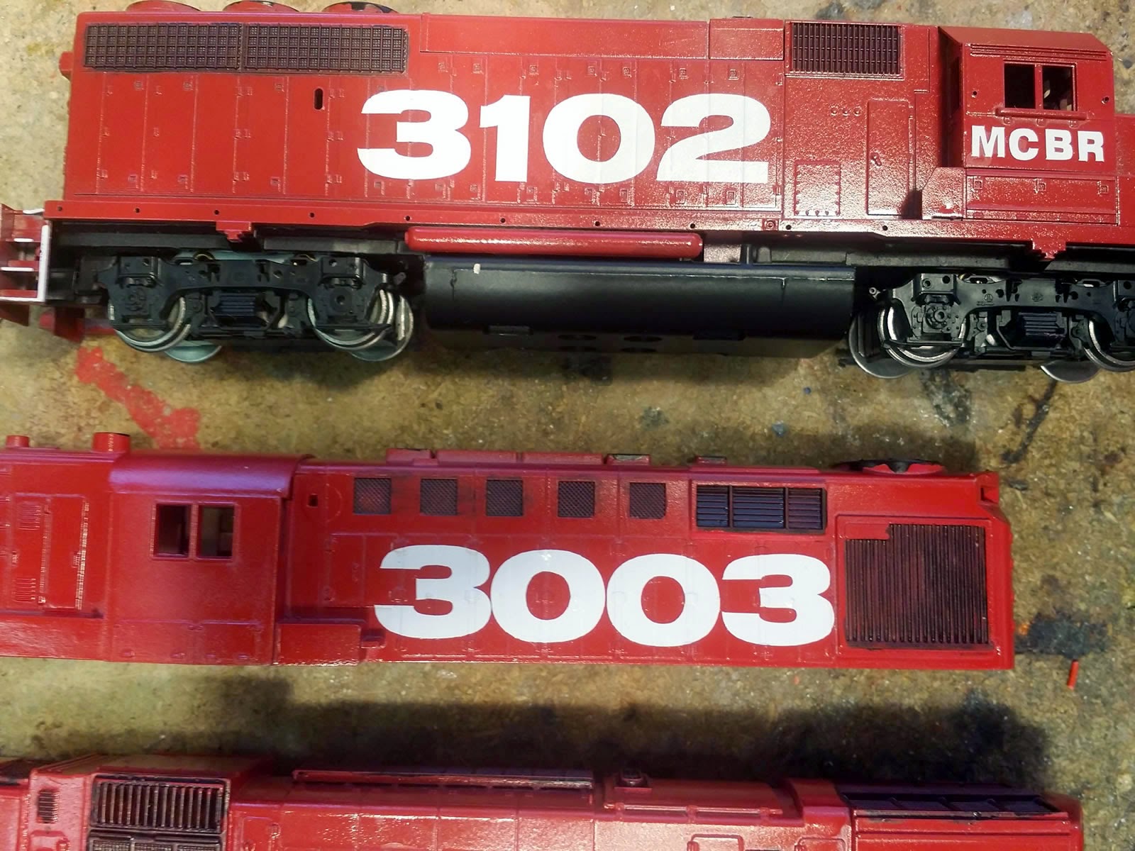
I've been experimenting with my Cricut Explore and cutting decals.  One of the things I decided to do on my new railroad was to have huge numbers on the side of each locomotive.  This accomplishes something important....namely makes it easy for me to see the number of the locomotive I want to work with.

There really aren't any decent ready made decals to do what I want to do so I decided I would give my Cricut Explore a shot at cutting numbers on blank white water slide decal paper.

First I tried printing a yellow box and cutting out the numbers so I could have them all be yellow.  This didn't really work out because once you clear coat the decals, solvaset has a tough time forming them.  So I decided to take the path of least resistance and make them white.  I'm quite pleased with the results.

In the future I'll revisit colored cuts, but for now take a look at my white numbers....

One note:  working with decals much larger than normal poses its own challenges.  Never use solvaset until you are sure you have the decals in position, if you do you'll be doing it over.

Here's some pix.....


Friday, September 5, 2014

HO Scale Working Hump Yard


So I have this test track and it sits on the carpet running round the edge of a room.  I used the the Life-Like Power Loc and some Life-Like flex track to build it.  Along 1 wall the track runs about 10' on flex track that has some carpet tape to hold it in place.

At the corners where the curve starts I used Power Loc...2 sections 22'" then 2 sections 9" straight followed by 2 sections 22" radius curve again then back to straight.  Then the Power Loc continues around the next 2 curves and back to flex and back to Power Loc and then into the 10' section of flex.

For the transitions I used just plain old wood door shims with some carpet tape.  My daughter wanted a large cardboard tube for a tunnel where the track runs under a credenza so a couple more shims on each end of that.  Then there is a spot close to the wall where a couple shims where needed on the Power Loc curve due to a slight bulge in the carpet.

In total there are 7 grade changes  between ¼" and a ½".  It took a lot of tweaking to get this to work out just right.  When all couplers are correctly height adjusted everything works perfect.  This is one way I use to identify locomotives and rolling stock that have couplers to high or low.

I usually pull 15-20 cars in a train on this track with 2 locomotives.  I have just a handful of locomotives that can do it alone -  GG1 can pull anything I thrown at it with no problems at all, a Bachmann pancake motor GP38-2 High Nose can do it and my Tyco C630 Power Torques can do it also.  There are a couple others that will surprise you also, but I'll save that for later.

There is one section of uphill grade for about 10' that tests locomotives and plastic couplers.  I don't have a good solution for getting Kadee #5's in those locomotives because the Bachmann couplers fit perfect..  I'll think about that one later.

All of this experimenting has lead me to believe that I can construct a working hump yard, but not in the way you would think....

What I have in mind is this:  a long lead track of about 15' or more, probably with a very curvy form to fit the layout room shape.  Near the end, 3-6 car lengths back will be an under track magnet.  I'm not real sure on the position yet, but that's my first guess.

Instead up a traditional hump, what will be at the control tower will be a ½" grade change going down.  Cars that have been uncoupled and "placed" in push mode will be pushed off the grade change left to roll into the yard on the track set by the Tower Operator.

The Tower Operator will have the switch list and will direct the pusher when to uncouple a certain car or cut of cars.

This design is more along the line of Gravity Yards, rather than true hump yards.  Here is a link to wikipedia article that has a blurb on Gravity Yards http://en.wikipedia.org/wiki/Classification_yard

I've identified 2 problems on my test track already....metal wheelsets will roll freely and crash into the car ahead on its track, or if the first car, it can roll past the end of the bowl.  A possible 1/8" grade change at the end fixes this, but there is a bit of rollback.  Not that big of a deal.

Plastic wheelsets that are really cheap may not roll at all or not far enough.  I have 2 solutions: 1.  Allow the Tower Operation to use the "magic stick" to push the car and 2. Have the bowl switcher come up and get it and bring it down into the bowl.  Obviously at the far end of the bowl there will need to be a switcher on hand to help tidy up the bowl.

One of the things I like about the design is that it takes 3 operators.  This meets one of my goals in that I want the layout to require lots of friends to come over and operate the thing.

Anyways this is something to chew on for a while - I'll be testing the concept in the near future and talk more about it then....

Thursday, July 24, 2014

Using Cricut Explore to make stencils for "patch" work


So I got kind of tired of making decals for everything, especially patch jobs on freight cars where I want different numbers on everything.  I was cleaning my supply closet and found some stencils I used to use in the Army on all kinds of gear.  This gave me an idea.....

Since I model a Belt Railway which has to get lots of stuff second hand, it occurred to me that a set of old Milwaukee Road 50' box cars that I had might make good "patch" jobs.  Rather than send the cars through the paint shop, I made some stencils using my Cricut Explore and just taped them onto the sides and sprayed some new reporting marks and numbers on each car.  It turned out pretty decent.

So here are some pix I made from the project:


Above is 3 Rail Box cars that I did this way and a screenshot of how it looks in the software...


And that's about all there is to it....